Table of Contents
Fabric-Formed Concrete Systems
by Robert P Schmitz, P.E.
Summary
The experimental verification work for the fabric forming design procedure described in the author's paper has yet to be carried out. This article describes the proposed experimental process.
Project Description
Objectives
The objective of this research project is to seek answers to the following questions:
- Can a fabric be utilized in a flexible formwork to form a concrete member in a manner that has certain distinct advantages over the currently predominant method of forming concrete with a rigid formwork? Is a geotextile fabric well suited to serve as that component in the formwork or should other durable, cost effective fabrics be utilized or developed if none suitable are available?
- Can efficiencies using a flexible formwork be realized significantly enough to reduce our impact on the built environment in terms of materials and energy usage – is it sustainable? Depletion of natural resources, the energy required to produce products made from virgin materials and the resulting emission of greenhouse gases from their production are all factors which should drive us to look at a more efficient means of forming concrete members. There is a need for us, as a society, to reduce our carbon footprint.
- Can a flexible fabric formwork be used to design concrete members in a manner that would be practical and useful to the design community? The American Concrete Institute (ACI) presently provides guidance for rigid formwork design through their Committee 347 and in a publication, Formwork for Concrete (7th Ed.). If flexible fabric formwork systems are to be of practical use to the design community standards and guidelines for their use will have to be developed.
Goals
The short-term goals of this project are to:
- Objectively answer the questions we posed above and using a sound engineering basis and experimentation determine whether formwork capable of forming concrete structural members using a flexible fabric, as one of its key components, is a viable alternative forming system to rigid formwork system.
- Involve architectural, structural engineering and mechanical engineering students at both the undergraduate and graduate levels in the experiments which bring them together using an interdisciplinary approach. An approach that will spark the imagination of these students to think beyond the simple geometric concrete form.
The long-term goal of this project is to introduce the design community to a new system of concrete formwork that is more efficient and sustainable than those systems presently being used. If successful the introduction of this unique method of forming concrete will provide the design community of architects, engineers and designers the tools necessary to bring their dreams and ideas to fruition in a new and more sustainable way. It is expected that additional avenues for research will come to light as a result of this initial project.
Background
Concrete members have traditionally been cast using a rigid formwork. Although recently, ACI Committee 334 has introduced a guide for the construction of shells using inflated forms. Straightforward methods of analysis and design are available for the traditionally cast concrete member – be it a concrete floor, beam, wall or column member.
The use of a flexible formwork appears to be ill-suited for casting any concrete member. But, this method of casting concrete may in fact be used anywhere a rigid formwork is used and is beginning to attract attention as a method of construction. An article by Mark West, Director of the Centre for Architectural Structures Technology (C.A.S.T.) at the University of Manitoba, Canada, published in Concrete International [1] was the P.I.’s first introduction to flexible formwork. For the past several years, Professor West and his architectural students at C.A.S.T. have been exploring the use of flexible formwork for casting concrete wall panels and other members [2, 3]. There are not many people in the U.S. aware of this unique method of forming concrete and most of the research being conducted at the present time is in Canada, Chile, the Netherlands, Scotland, Belgium and Germany.
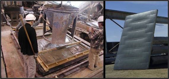
The casting of a full-scale panel using concrete requires finding a fabric capable of supporting the weight of the wet concrete. For this purpose, a geotextile fabric made of woven polypropylene fibers was utilized by C.A.S.T. The flexible fabric material was pre-tensioned in the formwork and assorted interior supports were added. Depending upon the configuration of these interior support conditions, three-dimensional funicular tension curves were produced in the fabric as it deformed under the weight of the wet concrete. Reinforcement added to the panel, as shown in Figure 1, only served to hold it together and was not for any particular loading condition.
This novel way of forming concrete has been experimented with by individuals and institutions internationally in recent years but little engineering analysis and system verification or validation through experimentation has been conducted. Due to the complex shapes that can be achieved with fabric forms their analysis is beyond the computational formulae currently used to calculate simple prismatically shaped member capacities. Prior to the P.I.’s initial research into this unique method of forming concrete no design procedures or methods to predict the deflected shape of a fabric cast concrete member had been developed. And, from an engineering point of view the challenge was to find a method to analyze the complex structural shape a fabric cast concrete wall panel could ultimately take. If a flexible formwork system is to be of practical use a method to analyze the forming system and the members produced by it must be put into place.
The P.I. has developed finite element procedures which allow one to model one type of structural member, a wall panel, and then analyze it for strength [4]. Procedures for the four step analytical modeling of a fabric formwork, loaded with the plastic concrete, are as follows:
- Determine the paths the lateral loads take to the points where the wall panel is to be anchored.
- Use the load paths, defined in Step 1, to model the fabric and plastic concrete material as 2 D and 3 D Solid elements, respectively. These elements are arranged to define the panel’s lines of support.
- “Form find” the final shape of the panel by incrementally increasing the thickness of the 3 D Solid elements until equilibrium in the supporting fabric formwork has been reached. This process is equivalent to achieving a flat surface in the actual concrete panel and could be compared to a ponding problem.
- Analyze and design the panel for strength requirements to resist the lateral live load and self weight dead load being imposed upon it.
By utilizing the above four step procedure, it is expected that obtaining an optimal panel shape is possible. The above procedure becomes an iterative process. If, after an analysis of the panel is made in Step 4, it is found that the panel is either “under strength” or too far “over strength”, adjustments to the model in Step 2 will be required and Steps 3 and 4 repeated. It is envisioned that this procedure might be extended to not only other structural member types but entire forming systems.
Advantages of geotextile fabric as formwork material include:
- Very complex shapes are possible. Designs are limited only by one’s imagination.
- Geotextile fabric is strong, lightweight, inexpensive and potentially reusable.
- Less concrete and reinforcing are required resulting in a more efficient and potentially sustainable design.
- Improved surface finish and durability of the concrete product are possible due to the filtering of air bubbles and excess bleed water through the fabric.
While geotextile fabric is not without disadvantages they are not thought to be insurmountable. Disadvantages include:
- Relaxation can occur due to the prestress forces in the membrane. There is also the potential for creep in the geotextile material, which can be accelerated by an increase in temperature as might occur during hydration of the concrete as it cures. Experimental results from this project should help to determine how much of an issue relaxation is and to what extent creep plays a role in the design process.
- The concrete must be placed carefully and the fabric formwork must not be jostled while the concrete is in a plastic state.
If it can be shown that a flexible formwork is indeed a cost effective, sustainable and viable method of forming concrete future research might explore the following:
- Formwork systems for various structural shapes e.g.; concrete floor, beam, wall or column members. Fabrics tailored to forming concrete with known and predictable properties.
- New fabrics with improved properties over those of geotextiles even more suited for use as a formwork component.
- Improved analytical tools for form-finding using finite element structural analysis software.
Proposed Research
The proposed research project will be conducted in several phases. Phases I and II will address question 1 posed in our project Objectives above:
- 1. Can a fabric be utilized in a flexible formwork to form a concrete member in a manner that has certain distinct advantages over the currently predominant method of forming concrete with a rigid formwork?
And Phase III will address questions 2 and 3 posed in our project Objectives above:
- 2. Can efficiencies using a flexible formwork be realized significantly enough to reduce our impact on the built environment in terms of materials and energy usage – is it sustainable?
- 3. Can a flexible fabric formwork be used to design concrete members in a manner that would be practical and useful to the design community?
Phase I – Proof of Concept
– Fabric as a Load Carrying Component
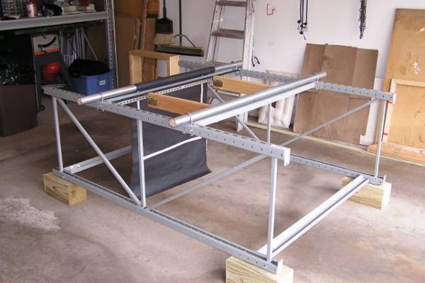
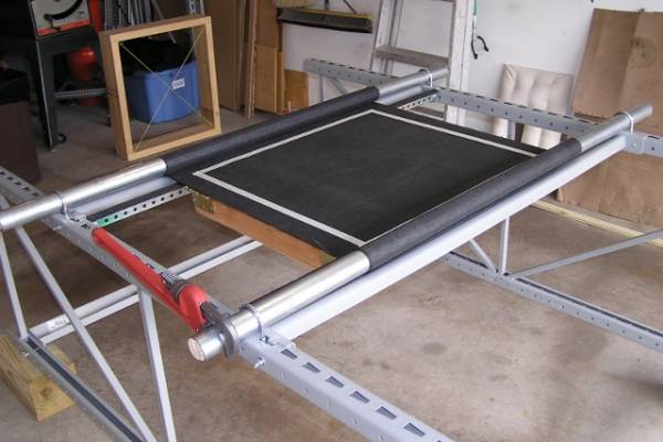
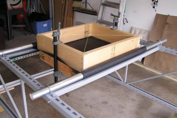
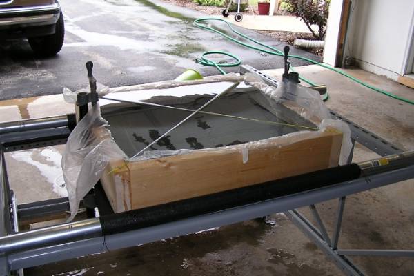
Tests will be conducted on simple “pillow” shaped panels with the fabric formwork placed into two states, one taut and one prestressed. Deflection of the fabric will be monitor using deflection gages (deflectometers). Relaxation of the geotextile fabric formwork under the prestressed state, prior to loading, will be monitored using a photogrammetric technique. Photogrammetry can be used to obtain, qualitative information on the geometry, displacement, and strain of a physical model in a noninvasive way. This technique is preferred over the use of bonded strain gages for analyzing strain since it eliminates the undue influence bonded strain gages have on the testing results. Since bonded strain gages are generally stronger than the material they are attached to they can adversely affect testing results. The technique is an inexpensive, high-resolution, noninvasive and efficient method that uses standard commercial software (PhotoModeler 6 [5]) and a digital camera. This technique will also be used to monitor fabric strain under load. See Figures 2 thru 5 for the proposed test frame setup.
For this Phase water will be used to load the fabric as shown in Figure 5. After each test is completed the panels will be unloaded and the fabric allowed to return to its original state. The reason for this is to determine whether the fabric can produce results that are consistent and repeatable. This will aid in determining whether the fabric may be reused.
The physical model will be analyzed analytically using a commercially available finite element analysis (FEA) software program, ADINA [6]. It is expected that results from experimental testing will allow for a more accurate input of geotextile material properties into the analytical model. Specifically, knowing how much the fabric relaxes during a given time period will help in establishing an adjusted value of the fabric’s modulus of elasticity.
Geotextile fabrics are anisotropic. That is the modulus of elasticity and strength of the fabric is different in each direction, machine direction (warp) and cross machine direction (fill). The higher the modulus of elasticity the less the fabric will deflect under load. As a result of testing it is hoped a more accurate prediction of displacement and thus the shape of the concrete panel are obtained in the analytical model.
Testing breakdown:
- Phase I – Test Series 1
- Panel size – 24 inches x 36 inches x 6 inches thick (609.6 mm x 914.4 mm x 152.4 mm thick)
- Six (6) fabric panels stretched to just a taut state
- Water loading
- Measurements taken
- deflection at geometric center
- fabric strain at selected locations
- load cell at each corner of test frame
- Panels loaded and unloaded for three (3) cycles
- Phase I – Test Series 2
- Panel size – 24 inches x 36 inches x 6 inches thick (609.6 mm x 914.4 mm x 152.4 mm thick)
- Six (6) fabric panels prestressed 1% in the 24 inch (609.6 mm) machine direction (warp) and just taut in the 36 inch (914.4 mm) cross machine direction (fill)
- Water loading
- Measurements taken
- initial prestress in fabric
- deflection at geometric center
- fabric strain at selected locations
- load cell at each corner of test frame
- Panels loaded and unloaded for three (3) cycles
- Phase I – Test Series 3
- Panel size – 24 inches x 36 inches x 6 inches thick (609.6 mm x 914.4 mm x 152.4 mm thick)
- Six (6) fabric panels prestressed 1.5% in the 24 inch (609.6 mm) machine direction (warp) and just taut in the 36 inch (914.4 mm) cross machine direction (fill)
- Water loading
- Measurements taken
- initial prestress in fabric
- deflection at geometric center
- fabric strain at selected locations
- load cell at each corner of test frame
- Panels loaded and unloaded for three (3) cycles
- Phase I – Test Series 4
- Panel size – 24 inches x 36 inches x 6 inches thick (609.6 mm x 914.4 mm x 152.4 mm thick)
- Six (6) fabric panels prestressed 2% in the 24 inch (609.6 mm) machine direction (warp) and just taut in the 36 inch (914.4 mm) cross machine direction (fill)
- Water loading
- Measurements taken
- initial prestress in fabric
- deflection at geometric center
- fabric strain at selected locations
- load cell at each corner of test frame
- Panels loaded and unloaded for three (3) cycles
Phase II – Proof of Concept
– Fabric as a Concrete Load Carrying Component
Using a test frame setup similar to that used for Phase I tests will be conducted on complex shaped panels with the fabric formwork placed into two states, taut and prestressed. The complex wall panel will introduce interior support points for the fabric. Deflection of the fabric will be monitor using deflection gages (deflectometers). Relaxation of the geotextile fabric formwork under the prestressed state and under load will again be monitored using the photogrammetric technique described above.
For this phase a plain concrete mix design will be utilized. After each test is completed the panels will be unloaded and the fabric allowed to return to its original state. The reason for this is to determine whether the fabric can produce results that are consistent and repeatable. This will aid in determining whether the fabric may be cleaned and reused.
Results from the experimental testing will be compared with those obtained from an analytical analysis using the finite element analysis program ADINA. Of interest here will be how well the experimental model compares with the analytical model in terms of:
- The total volume of concrete in the final panel shape.
- The strain in the fabric at selected panel points just prior to pouring the concrete and as the concrete cures.
- Deflection of the fabric and thus the thickness of the panel at selected panel points.
The temperature the concrete reaches during the heat of hydration will also be of interest. Levels above 100° F (37.8° C) are known to accelerate creep in geotextile fabrics [7]. Creep in the fabric and thus an increase in deflection may cause micro-cracking in the plastic concrete panel and thus have an adverse affect on its appearance, durability and performance.
Testing breakdown:
- Phase II – Test Series 1
- Panel size – 36 inches x 48 inches x 6 inches thick (914.4 mm x 1,219.4 mm x 152.4 mm thick)
- Six (6) fabric panels stretched to just a taut state
- Plain concrete loading
- Measurements taken
- deflection at selected locations
- fabric strain at selected locations
- thermal couples in concrete
- load cell at each corner of test frame
- Panels loaded and unloaded (fabric stripped) for three (3) cycles
- Phase II – Test Series 2
- Panel size – 36 inches x 48 inches x 6 inches thick (914.4 mm x 1,219.4 mm x 152.4 mm thick)
- Six (6) fabric panels prestressed 1% in the 36 inch (914.4 mm) machine direction (warp) and just taut in the 48 inch (1,219.4 mm) cross machine direction (fill)
- Plain concrete loading
- Measurements taken
- initial prestress in fabric
- deflection at selected locations
- fabric strain at selected locations
- thermal couples in concrete
- load cell at each corner of test frame
- load cell at each corner of test frame
- Panels loaded and unloaded (fabric stripped) for three (3) cycles
- Phase II – Test Series 3
- Panel size – 36 inches x 48 inches x 6 inches thick (914.4 mm x 1,219.4 mm x 152.4 mm thick)
- Six (6) fabric panels prestressed 1.5% in the 36 inch (914.4 mm) machine direction (warp) and just taut in the 48 inch (1,219.4 mm) cross machine direction (fill)
- Plain concrete loading
- Measurements taken
- initial prestress in fabric
- deflection at selected locations
- fabric strain at selected locations
- thermal couples in concrete
- load cell at each corner of test frame
- Panels loaded and unloaded (fabric stripped) for three (3) cycles
- Phase II – Test Series 4
- Panel size – 36 inches x 48 inches x 6 inches thick (914.4 mm x 1,219.4 mm x 152.4 mm thick)
- Six (6) fabric panels prestressed 2% in the 36 inch (914.4 mm) machine direction (warp) and just taut in the 48 inch (1,219.4 mm) cross machine direction (fill)
- Plain concrete loading
- Measurements taken
- initial prestress in fabric
- deflection at selected locations
- fabric strain at selected locations
- thermal couples in concrete
- load cell at each corner of test frame
- Panels loaded and unloaded (fabric stripped) for three (3) cycles
Phase III – Proof of Concept
– Fabric Used to Form a Practical Load Carrying Component
For this phase of the project full-scale concrete wall panels will be designed, constructed and tested for lateral load carrying capacity. The results of control panels constructed using plain concrete will be compared with those reinforced with steel or fiberglass reinforced polymer (FRP) reinforcing bars. Results from the experimental testing will be compared with those obtained from an analytical analysis using the finite element analysis program ADINA.
Aesthetics may play a large role in the acceptance and desirability of these fabric-formed panels but one of the key issues we will wish to address is that of efficiency. To that end the theoretical capacity of a normally reinforced concrete panel formed in a rigid formwork will be compared to the theoretical capacity of the fabric-formed panel using the FEA program ADINA. Experimental capacities from our test results will also be compared with the theoretical results.
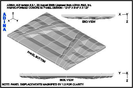
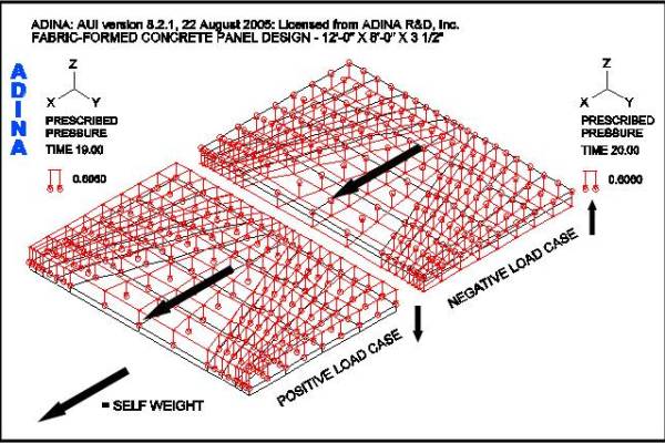
Figure 6 shows the analytical model after form-finding and Figure 7 shows the load cases. The complex wall panel will introduce interior supports for the fabric.
Testing breakdown:
- Phase III – Test Series 1 (Control Panel)
- Panel size – 12’-0” x 8’-0” x 3½”-thick (3.7 m x 2.4 m x 88.9 mm thick)
- Six (6) fabric panels prestressed 2% in the 8’-0” (2.4m) machine direction (warp) and just taut in the 12’-0” (3.7 m) cross machine direction (fill), three (3) panels for positive loads and three (3) panels for negative loads
- Plain concrete mix
- Measurements taken during forming
- initial prestress in fabric
- deflection at selected locations
- thermal couples in concrete
- fabric strain at selected locations
- load cell at each corner of test frame
- Panels stripped from fabric and loaded laterally to simulate positive and negative wind loads (uniform load applied using vacuum chamber)
- Measurements taken during lateral loading
- deflection at selected locations
- concrete strain at selected locations
- load cell at panel reaction points
- Phase III – Test Series 2 (Reinforced Panel)
- Panel size – 12’-0” x 8’-0” x 3½”-thick (3.7 m x 2.4 m x 88.9 mm thick)
- Six (6) fabric panels prestressed 2% in the 8’-0” (2.4 m) machine direction (warp) and just taut in the 12’-0” (3.7 m) cross machine direction (fill), three (3) panels for positive loads and three (3) panels for negative loads
- FRP or steel reinforced concrete panel
- Measurements taken during forming
- initial prestress in fabric
- deflection at selected locations
- thermal couples in concrete
- fabric strain at selected locations
- load cell at each corner of test frame
- Panels stripped from fabric and loaded laterally to simulate positive and negative wind loads (uniform load applied using vacuum chamber)
- Measurements taken during lateral loading
- deflection at selected locations
- concrete strain at selected locations
- load cell at panel reaction points
Testing Difficulties
For Phase III testing of full-scale concrete wall panels may be difficult given the capacities of the vacuum chamber equipment we are able to configure. While it would be preferred to test a full-scale panel similar to one that would be used in a practical application it is believed that acceptable results and conclusions will be obtained from scaled down panels as well.
See Also
References
[1] West, Mark. “Fabric Formed Concrete Members.” Concrete International Vol. 25(10), pp. 55+. October 2003.
[2] West, Mark. “Fabric Cast Concrete Wall Panels.” Materials Technology Workshop, Department of Architecture, University of Manitoba, Canada. [Internet, WWW]. Address: http://www.umanitoba.ca/cast_building/. April 2002.
[3] West, Mark. “Prestressed Fabric Formwork for Precast Concrete Panels.” Concrete International Vol. 26(4), pp. 60+. April 2004.
[4] Schmitz, Robert. “Fabric Formed Concrete Panel Design.” Master’s thesis, Milwaukee School of Engineering, Milwaukee, Wisconsin 53202. 2004.
[5] EOS Systems, Inc. PhotoModeler (Version 6.3.3). [Computer program]. Available: EOS Systems, Inc., 210-1847 West Broadway, Vancouver BC V6J IY6 Canada. April 2009.
[6] ADINA R & D, Inc. ADINA (Version 8.5). [Computer program]. Available: ADINA R & D, Inc., 71 Elton Avenue, Watertown, Massachusetts 02472. September 2008.
[7] Terram Ltd., “Designing for Soil Reinforcement (Steep Slopes),” Handbook, (United Kingdom: Terram Ltd.), pp. 19-22. May 2000.
